QRS axis and voltage
Editor-In-Chief: C. Michael Gibson, M.S., M.D. [1]; Associate Editor-In-Chief: Cafer Zorkun, M.D., Ph.D. [2]
Overview
The electrical heart axis is an average of all electrical depolarization in the heart. The depolarization wave begins in the right atrium and proceeds toward the left and right ventricle. Because the left ventricle wall is thicker than the right wall, the arrow indicating the direction of the depolarization wave is directed toward the left.
How do you determine the electrical heart axis
When you average all electrical signals from the heart, you can indicate the direction of the average electrical depolarization with an arrow (vector). This is the hear taxis. Especially a change of the heart axis or an extreme deviation can be an indication for pathology. For example:
- Biggest QRS deflection in lead I: the electrical activity is directed to the left (of the patient)
- Biggest QRS deflection in lead AVF: the electrical activity is directed down.
This indicates a normal heartaxis. Usually, these two leads are enough to diagnose a normal heart axis.
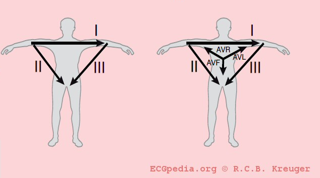
The biggest vector in the heart is from the AV-node in the direction of the ventricular depolarization. Under normal circumstances, this is directed left and down.(towards leads I and aVF).
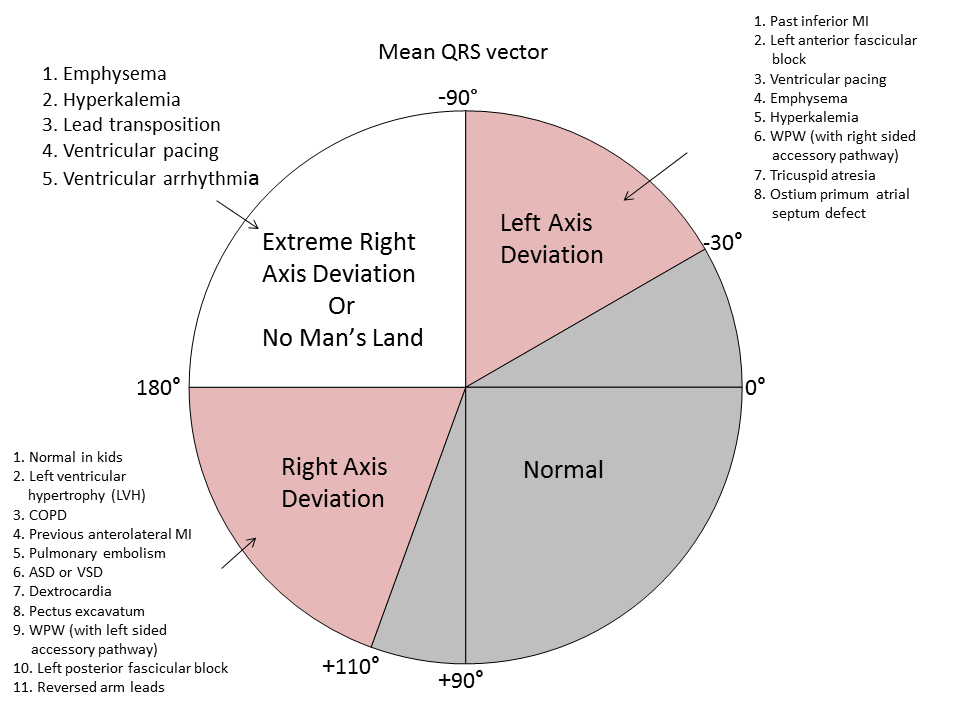
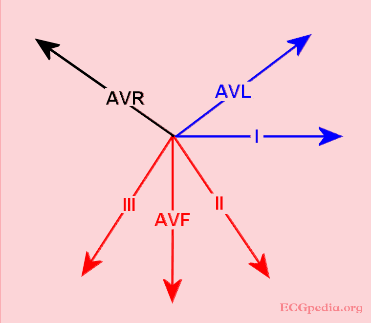
The position of the QRS vector is given in degrees. See the figure, the middle of the figure is the AV-node. A horizontal line towards the left arm is defined as 0 degrees.
A normal heart axis is between -30 and +90 degrees.
Rule: biggest QRS deflection in I and II is an intermediate = normal heart axis. So positive deflections in I and II indicates a normal heart axis.
<flashow>http://nl.ecgpedia.org/images/c/cc/Heartaxis.swf%7Cheight=350px%7Cwidth=600px</flashow> Click and drag the arrow in the above animation to change the heart axis and see how the ECG changes.
The electrical heart axis is an average of all depolarizations in the heart. The depolarization wave begins in the right atrium and proceeds to the left and right ventricle. Because the left ventricle wall is thicker than the right wall, the arrow indicating the direction of the depolarization wave is directed to the left.
The QRS Axis
Interpretation
The interpretation of the electrical heart axis has a few rules of thumb:
- First, when a positive depolarization wave moves towards a positive electrode, a positive, upwards deflection is registered on the ECG.
- Second, there are 4 quadrants where the QRS-vector can point to:
- left upper quadrant --> left axis deviation (between -30º and -90º)
- left lower quadrant --> normal (between -30º and 90º)
- right below and right --> right axis deviation (between 90º and -150º)
- right upper quadrant --> extreme axis (between -90º and -150º)
'No Man's Land' aka 'Northwest Axis' (-90 to -180)
Right Axis Deviation (+90 to +180)
- Normal in kids and tall, thin adults
- Right ventricular hypertrophy (RVH)
- Chronic obstructive pulmonary disease (COPD)
- Previous anterolateral MI
- Left posterior fascicular block
- Pulmonary embolism
- WPW with left-sided accessory pathway
- Atrial Septal Defect or Ventricular Septal Defect
- Pectus excavatum
- Dextrocardia
- Reversed arm leads
Left Axis Deviation (-30 to -90)
- Past inferior MI
- Left anterior fascicular block
- Ventricular pacing
- Emphysema
- Hyperkalemia
- WPW with right-sided accessory pathway
- Tricuspid atresia
- Ostium primum atrial septal defect
Examples
The QRS in lead I, will have a negative deflection in a right axis deviation. The vector is not directed towards the electrode. However, lead AVF will be positive, the vector is directed towards the electrode.
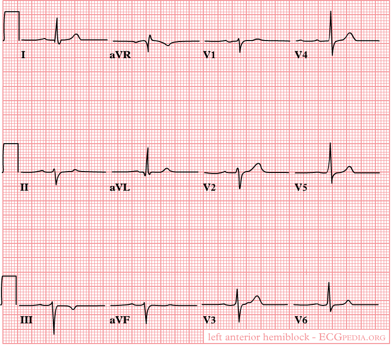
Image:hartas2.jpg|The heart axis indicates the average direction of the depolarization wave. A normal heart axis, the picture shows an example, is between -30 and +90 degrees. In this example, the heart axis is +45 degrees.
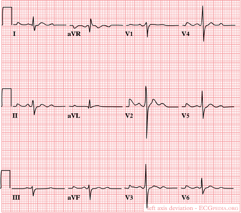
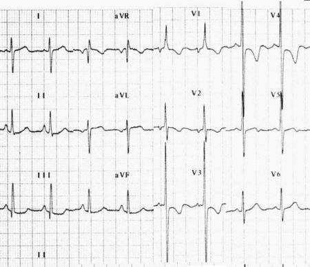
Image:left_axis_dev.jpg|Heart axis deviation to the left in case of an inferior myocardial infarction. Left anterior hemiblock is a common cause. A left axis is between -30 and -90 degrees. The axis is -30 degrees.
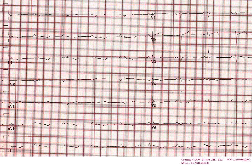
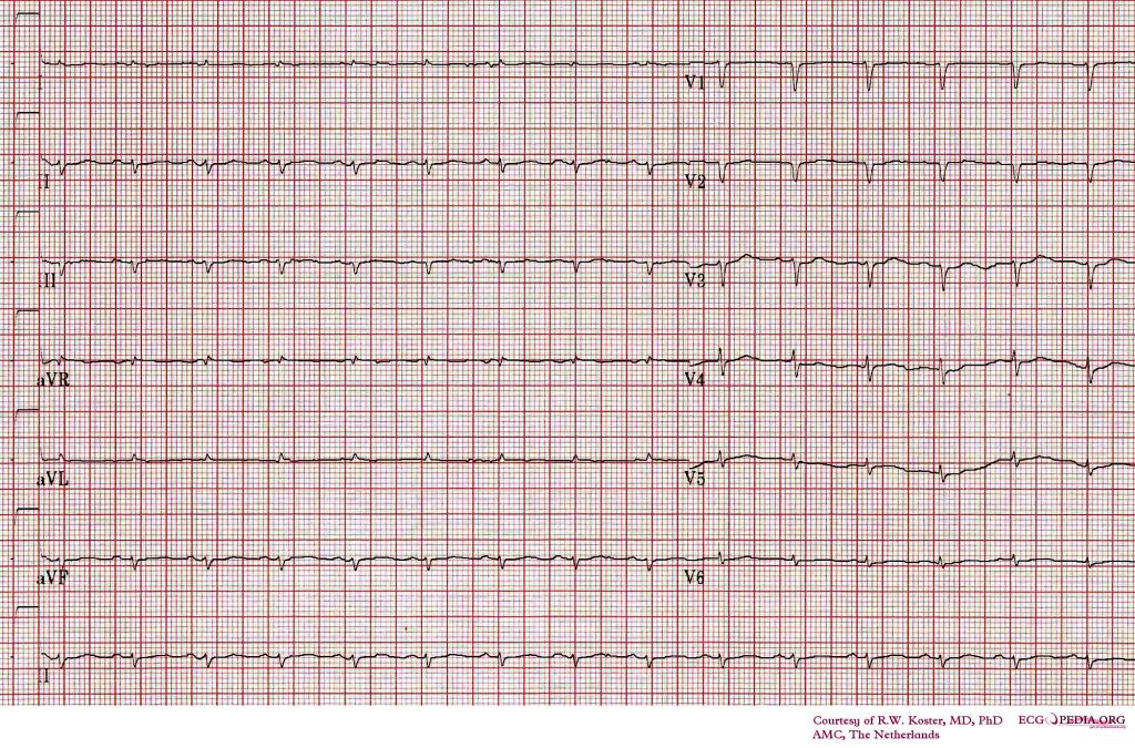
Image:right_axis_dev.jpg|Heart axis deviation to the right in right ventricular load, as in chronic obstructive pulmonary disease (COPD) or pulmonary embolism. A right axis is between +90 and +180 degrees. In this case the axis is +135 degrees
Heart axis Simulator
To understand how the ECG changes in axis deviations, this excellent axis-simulator may be helpful: http://www.blaufuss.org/ECGviewer/indexFrame2.html
Iso-electrical
Note: When the depolarization is perpendicular on the lead, this is called iso-electrical. The QRS is neither positive nor negative.
Undetermined axis
When all extremity leads are biphasic, the axis is directed to the front or back, in a transverse plane. The axis is than undetermined or indeterminate.
Abnormal heart axis
The direction of the vector can changes under different circumstances:
- When the heart itself is rotated (right ventricular overload), obviously the axis turns with it.
- In case of ventricular hypertrophy, the axis will deviate by the bigger electrical activity and the vector will turn towards the hypertrophied tissue.
- Infarcted tissue is electrically dead. No electrical activity is registered and the QRS vector turns away from the infracted tissue
- In conduction problems, the axis deviates too. When the right ventricle depolarizes later than the left ventricle, the axis will turn to the right (RBBB). This is because the right ventricle will begin the contraction later and therefore will also finish later. In a normal situation the vector is influenced by the left ventricle but now only by the right ventricle.
Examples of a left heart axis
- left anterior fascicular block
- Inferior myocardial infarction
- Left ventricular hypertrophy
- Pacemaker rhythm
Examples of a right heart axis
- Right ventricular hypertrophy
- Right ventricular load, for example Pulmonary Embolism or Cor pulmonale (as in COPD)
- Atrial septal defect, ventricular septal defect
Microvoltages
The QRS amplitute (i.e. the sum of the postive and negative parts) in the limb leads does not exceed 0.5 mV (5 mm) OR is no more than 1.0 mV (1 cm) in the chest leads.
Possible causes of microvoltages
- Cardiomyopathy, especially infiltrative cardiomyopathy, such as in amyloidosis
- Increased resistance between the heart and the electrodes: pneumothorax, obesity, pericardial fluid / tamponade, pleural effusion
- Myocarditis / pericarditis
- Heart tranplantation, especially during acute or chronic rejection
- Wrong settings on the ECG apparatus (sensitivity should be at 10 mm/mV)
External links
- Ventricular Electrocardiography
- The Basis of ECG Diagnosis
- Distortion Factors in the ECG
- 12-Lead ECG System
- Anatomy and Physiology of the Heart