Artificial pacemaker


Editor-In-Chief: C. Michael Gibson, M.S., M.D. [1]; Associate Editor-In-Chief: Cafer Zorkun, M.D., Ph.D. [2]
Overview
A pacemaker (or artificial pacemaker, so as not to be confused with the heart's natural pacemaker) is a medical device which uses electrical impulses, delivered by electrodes contacting the heart muscles, to regulate the beating of the heart. The primary purpose of a pacemaker is to maintain an adequate heart rate, either because the heart's native pacemaker is not fast enough, or there is a block in the heart's electrical conduction system. Modern pacemakers are externally programmable and allow the cardiologist to select the optimum pacing modes for individual patients. Some combine a pacemaker and implantable defibrillator in a single implantable device. Others have multiple electrodes stimulating differing positions within the heart to improve synchronisation of the lower chambers of the heart.
History of the Artificial Pacemaker

The preceding implantable devices all suffered from the unreliability and short lifetime of the available primary cell technology which was mainly that of the mercury battery.
In 1889 J A McWilliam reported in the British Medical Journal of his experiments in which application of an electrical impulse to the human heart in asystole caused a ventricular contraction and that a heart rhythm of 60-70 beats per minute could be evoked by impulses applied at spacings equal to 60-70/minute.[1]
In 1928 Dr Mark C Lidwell of the Royal Prince Alfred Hospital of Sydney, supported by physicist Edgar H Booth of the University of Sydney, devised a portable apparatus which "plugged into a lighting point" and in which "One pole was applied to a skin pad soaked in strong salt solution" while the other pole "consisted of a needle insulated except at its point, and was plunged into the appropriate cardiac chamber". "The pacemaker rate was variable from about 80 to 120 pulses per minute, and likewise the voltage variable from 1.5 to 120 volts" The apparatus was used to revive a stillborn infant at Crown Street Women's Hospital, Sydney whose heart continued "to beat on its own accord", "at the end of 10 minutes" of stimulation.[2][3]
In 1932 American physiologist Albert Hyman, working independently, described an electro-mechanical instrument of his own, powered by a spring-wound hand-cranked motor. Hyman himself referred to his invention as an "artificial pacemaker", the term continuing in use to this day.[4][5]
An apparent hiatus in publication of research conducted between the early 1930s and World War II may be attributed to the public perception of interfering with nature by 'reviving the dead'. For example, "Hyman did not publish data on the use of his pacemaker in humans because of adverse publicity, both among his fellow physicians, and due to newspaper reporting at the time. Lidwell may have been aware of this and did not proceed with his experiments in humans".[3]
An external pacemaker was designed and built by the Canadian electrical engineer John Hopps in 1950 based upon observations by cardio-thoracic surgeon Wilfred Gordon Bigelow at Toronto General Hospital . A substantial external device using vacuum tube technology to provide transcutaneous pacing, it was somewhat crude and painful to the patient in use and, being powered from an AC wall socket, carried a potential hazard of electrocution of the patient by inducing ventricular fibrillation.
A number of innovators, including Paul Zoll, made smaller but still bulky transcutaneous pacing devices in the following years using a large rechargeable battery as the power supply.[6]
In 1957 Dr. William L. Weirich published the results of research performed at the University of Minnesota. These studies demonstrated the restoration of heart rate, cardiac output and mean aortic pressures in animal subjects with complete heart block through the use of a myocardial electrode. This effective control of post surgical heart block proved to be a significant contribution to decreasing mortality of open heart surgery in this time period.[7]
The development of the transistor and its first commercial availability in 1956 was the pivotal event which led to rapid development of practical cardiac pacemaking.
In 1957 engineer Earl Bakken of Minneapolis, Minnesota, produced the first wearable external pacemaker for a patient of Dr. C. Walton Lillehei. This transistorized pacemaker, housed in a small plastic box, had controls to permit adjustment of pacing heart rate and output voltage and was connected to electrode leads which passed through the skin of the patient to terminate in electrodes attached to the surface of the myocardium of the heart.
The first clinical implantation into a human of a fully implantable pacemaker was in 1958 at the Karolinska University Hospital in Solna, Sweden, using a pacemaker designed by Rune Elmqvist and surgeon Åke Senning, connected to electrodes attached to the myocardium of the heart by thoracotomy . The device failed after three hours. A second device was then implanted which lasted for two days. The world's first implantable pacemaker patient, Arne Larsson, survived the first tests and died in 2001 after having received 22 different pacemakers during his lifetime.
In 1959 temporary transvenous pacing was first demonstrated by Furman et al in which the catheter electrode was inserted via the patient's basilic vein.[8]
In February,1960, an improved version of the Swedish Elmqvist design was implanted in Montevideo, Uruguay in the Casmu Hospital by Doctors Fiandra and Rubio. That device lasted until the patient died of other ailments, 9 months later. The early Swedish-designed devices used rechargeable batteries, which were charged by an induction coil from the outside.
Implantable pacemakers constructed by engineer Wilson Greatbatch entered use in humans from April 1960 following extensive animal testing. The Greatbatch innovation varied from the earlier Swedish devices in using primary cells (mercury battery) as the energy source. The first patient lived for a further 18 months.
The first use of transvenous pacing in conjunction with an implanted pacemaker was by Parsonnet in the USA [9][10], Lageren in Sweden[11][12] and Jean-Jaques Welti in France[13] in 1962-63.
The transvenous, or pervenous, procedure involved incision of a vein into which was inserted the catheter electrode lead under fluoroscopic guidance, until it was lodged within the trabeculae of the right ventricle. This method was to become the method of choice by the mid-1960s.
The preceding implantable devices all suffered from the unreliability and short lifetime of the available primary cell technology which was mainly that of the mercury battery.
In the late 1960s several companies, including ARCO in the USA, developed isotope powered pacemakers, but this development was overtaken by the development in 1970 of the lithium-iodide cell by Wilson Greatbatch. Lithium-iodide or lithium anode cells became the standard for future pacemaker designs.
A further impediment to reliability of the early devices was the diffusion of water vapour from the body fluids through the epoxy resin encapsulation affecting the electronic circuitry. This phenomenon was overcome by encasing the pacemaker generator in an hermetically sealed metal case, initially by Telectronics of Australia in 1969 followed by Cardiac Pacemakers Inc of Minneapolis in 1972. This technology, using titanium as the encasing metal, became the standard by the mid-1970s.
Others who contributed significantly to the technological development of the pacemaker in the pioneering years were Bob Anderson of Medtronic Minneapolis, J.G (Geoffrey) Davies of St George's Hospital London, Barouh Berkovits and Sheldon Thaler of American Optical, Geoffrey Wickham of Telectronics Australia, Walter Keller of Cordis Corp. of Miami, Hans Thornander who joined previously mentioned Rune Elmquist of Elema-Schonander in Sweden, Janwillem van den Berg of Holland and Anthony Adducci of Cardiac Pacemakers Inc.(Guidant)
Indications
Artificial pacemakers can be used in order to help with and/or treat these conditions:
- Sinus node dysfunction - when the sinoatrial node does not fire properly to contract the heart
- Bifascicular block, trifascicular block, or third degree AV block.
- Stokes-Adams attack involving disruption of conduction between the sinoatrial node and the atrioventricular node.
Methods of Pacing
Percussive Pacing
Percussive Pacing, also known as Transthoracic Mechanical Pacing, is the use of the closed fist, usually on the left lower edge of the sternum over the right ventricle, striking from a distance of 20 - 30 cm to induce a ventricular beat (the British Journal of Anesthesia suggests this must be done to raise the ventricular pressure 10 - 15mmhg to induce electrical activity). This is an old procedure used only as a life saving means until an electrical pacemaker is brought to the patient.[14]
Transcutaneous Pacing
Transcutaneous pacing (TCP), also called external pacing, is recommended for the initial stabilization of hemodynamically significant bradycardias of all types. The procedure is performed by placing two pacing pads on the patient's chest, either in the anterior/lateral position or the anterior/posterior position. The rescuer selects the pacing rate, and gradually increases the pacing current (measured in mA) until electrical capture (characterized by a wide QRS complex with a tall, broad T wave on the ECG) is achieved, with a corresponding pulse. Pacing artifact on the ECG and severe muscle twitching may make this determination difficult. External pacing should not be relied upon for an extended period of time. It is an emergency procedure that acts as a bridge until transvenous pacing or other therapies can be applied.
Epicardial Pacing (temporary)
Temporary epicardial pacing is used during open heart surgery should the surgical procedure create atrio ventricular block. The electrodes are placed in contact with the outer wall of the ventricle (epicardium) to maintain satisfactory cardiac output until a temporary transvenous electrode has been inserted.
Transvenous Pacing (temporary)
Transvenous pacing, when used for temporary pacing, is an alternative to transcutaneous pacing. A pacemaker wire is placed into a vein, under sterile conditions, and then passed into either the right atrium or right ventricle. The pacing wire is then connected to an external pacemaker outside the body. Transvenous pacing is often used as a bridge to permanent pacemaker placement. It can be kept in place until a permanent pacemaker is implanted or until there is no longer a need for a pacemaker and then it is removed.
Permanent Pacing

Permanent pacing with an implantable pacemaker involves transvenous placement of one or more pacing electrodes within a chamber, or chambers, of the heart. The procedure is performed by incision of a suitable vein into which the electrode lead is inserted and passed along the vein, through the valve of the heart, until positioned in the chamber. The procedure is facilitated by fluoroscopy which enables the physician or cardiologist to view the passage of the electrode lead. After satisfactory lodgment of the electrode is confirmed the opposite end of the electrode lead is connected to the pacemaker generator.
The pacemaker generator is an hermetically sealed device containing a power source, usually a lithium battery, a sensing amplifier which processes the electrical manifestation of naturally occurring heart beats as sensed by the heart electrodes, the computer logic for the pacemaker and the output circuitry which delivers the pacing impulse to the electrodes.
Most commonly, the generator is placed below the subcutaneous fat of the chest wall, above the muscles and bones of the chest. However, the placement may vary on a case by case basis.
The outer casing of pacemakers is so designed that it will rarely be rejected by the body's immune system. It is usually made of titanium, which is inert in the body.
Basic Pacemaker Function
Modern pacemakers usually have multiple functions. The most basic form monitors the heart's native electrical rhythm. When the pacemaker doesn't sense a heartbeat within a normal beat-to-beat time period, it will stimulate the ventricle of the heart with a short low voltage pulse. This sensing and stimulating activity continues on a beat by beat basis.
The more complex forms include the ability to sense and/or stimulate both the atrial and ventricular chambers.
| I | II | III | IV | V |
|---|---|---|---|---|
| Chamber(s) paced | Chamber(s) sensed | Response to sensing | Rate modulation | Multisite pacing |
| O = None | O = None | O = None | O = None | O = None |
| A = Atrium | A = Atrium | T = Triggered | R = Rate modulation | A = Atrium |
| V = Ventricle | V = Ventricle | I = Inhibited | V = Ventricle | |
| D = Dual (A+V) | D = Dual (A+V) | D = Dual (T+I) | D = Dual (A+V) |
Biventricular Pacing (BVP)
A biventricular pacemaker, also known as CRT (cardiac resynchronization therapy) is a type of pacemaker that can pace both the septal and lateral walls of the left ventricle. By pacing both sides of the left ventricle, the pacemaker can resynchronize a heart whose opposing walls do not contract in synchrony, which occurs in approximately 25-50 % of heart failure patients.
CRT devices have at least two leads, one in the right ventricle to stimulate the septum, and another inserted through the coronary sinus to pace the lateral wall of the left ventricle. Often, for patients in normal sinus rhythm, there is also a lead in the right atrium to facilitate synchrony with the atrial contraction. Thus, timing between the atrial and ventricular contractions, as well as between the septal and lateral walls of the left ventricle can be adjusted to achieve optimal cardiac function.
CRT devices have been shown to reduce mortality and improve quality of life in patients with heart failure symptoms; a LV ejection fraction less than or equal to 35% and QRS duration on EKG of 120 msec or greater.[16][17][18] CRT can be combined with an implantable cardioverter-defibrillator (ICD).[19]

Advancements in Pacemaker Function

One unrealized advancement in pacemaker function could mimic nature by utilizing various bodily input parameters such as CO2 - O2 at in arterial-vein system, body temperature, ATP levels, Adrenaline, etc. Instead of producing a static, predetermined heart rate, or intermittent control, a Dynamic Pacemaker could compensate for both actual respiratory loading and potentially anticipated respiratory loading. A Dynamic Pacemaker would require sensory technology for which heart-rate regulation parameters must first be acutely identified. Dynamic Pacemaking technology could also be applied to future artificial hearts. Advances in transitional tissue welding would support this and other artificial organ/joint/tissue replacement efforts. Stem cells may or may not be of interest to transitional tissue welding.
When first invented, pacemakers controlled only the rate at which the heart's two largest chambers, the ventricles, beat.
Many advancements have been made to enhance the control of the pacemaker once implanted. Many of these enhancements have been made possible by the transition to microprocessor controlled pacemakers. Pacemakers that control not only the ventricles but the atria as well have become common. Pacemakers that control both the atria and ventricles are called dual-chamber pacemakers. Although these dual-chamber models are usually more expensive, timing the contractions of the atria to precede that of the ventricles improves the pumping efficiency of the heart and can be useful in congestive heart failure.
Rate responsive pacing allows the device to sense the physical activity of the patient and respond appropriately by increasing or decreasing the base pacing rate via rate response algorithms.
The DAVID trials[20] have shown that unnecessary pacing of the right ventricle can lead to heart failure and an increased incidence of atrial fibrillation. The newer dual chamber devices can keep the amount of right ventricle pacing to a minimum and thus prevent worsening of the heart disease.
Other Devices with Pacemaker Function
Sometimes devices resembling pacemakers, called ICDs (implantable cardioverter-defibrillators) are implanted. These devices are often used in the treatment of patients at risk from sudden cardiac death. An ICD has the ability to treat many types of heart rhythm disturbances by means of pacing, cardioversion, or defibrillation.
| I | II | III | IV |
|---|---|---|---|
| Shock chamber | Antitachycardia pacing chamber | Tachycardia detection | Antibradycardia pacing chamber |
| O = None | O = None | E = Electrogram | O = None |
| A = Atrium | A = Atrium | H = Hemodynamic | A = Atrium |
| V = Ventricle | V = Ventricle | V = Ventricle | |
| D = Dual (A+V) | D = Dual (A+V) | D = Dual (A+V) |
| ICD-S | ICD with shock capability only |
| ICD-B | ICD with bradycardia pacing as well as shock |
| ICD-T | ICD with tachycardia (and bradycardia) pacing as well as shock |
Patient Considerations
Insertion

A pacemaker is typically inserted into the patient through a simple surgery using a local anesthetic. The patient is usually given a drug for relaxation. An incision is made in the left shoulder area below the collar bone where the pacemaker is actually housed in the patient's body. The lead or leads (the number of leads varies depending on the type of pacemaker) are fed into the heart through a large vein using a fluoroscope to monitor the progress of lead insertion. A temporary drain may be installed and removed the following day. The actual surgery may take about an hour.
The patient should exercise reasonable care about the wound as it heals.
Following surgery there is a followup session during which the pacemaker is checked using a "programmer" that can communicate with the device and allows a health care professional to evaluate the system's integrity and determine the settings such as pacing voltage output.

Pacemaker Patient Identification Card
International Pacemaker Patient Identification Cards carry information such as; patient data (between others, symptom primary, ECG, aetiology), pacemaker center (doctor, hospital), IPG (rate, mode, date of implantation, MFG, type) and lead [22] [23].
Living with a Pacemaker
Periodic Pacemaker Checkups

Once the pacemaker is implanted, it is periodically checked to ensure the device is operational and performing appropriately. Depending on the frequency set by the following physician, the device can be checked as often as is necessary. Routine pacemaker checks are typically done in-office every six (6) months, though will vary depending upon patient/device status and remote monitoring availability.
At the time of in-office follow-up, the device will be interrogated to perform diagnostic testing. These tests include:
- Sensing: the ability of the device to "see" intrinsic cardiac activity (Atrial and ventricular depolarization).
- Impedance: A test to measure lead integrity. Large and/or sudden increases in impedance can be indicative of a lead fracture while large and/or sudden decreases in impedance can signify a breach in lead insulation.
- Threshold: this test confirms the minimum amount of energy (Both volts and pulse width) required to reliably depolarize (capture) the chamber being tested. Determining the threshold allows the Allied Professional, Representative, or Physician to program an output that recognizes an appropriate safety margin while optimizing device longevity.
As modern pacemakers are "on-demand", meaning that they only pace when necessary, device longevity is affected by how much it is utilized. Other factors affecting device longevity include programmed output and algorithms (features) causing a higher level of current drain from the battery.
An additional aspect of the in-office check is to examine any events that were stored since the last follow-up. These are typically stored based on specific criteria set by the physician and specific to the patient. Some devices have the availability to display intracardiac electrograms of the onset of the event as well as the event itself. This is especially helpful in diagnosing the cause or origin of the event and making any necessary programming changes.
Lifestyle Considerations
A patient's lifestyle is usually not modified to any great degree after insertion of a pacemaker. There are a few activities that are unwise such as full contact sports and activities that involve intense magnetic fields.
The pacemaker patient may find that some types of everyday actions need to be modified. For instance, the shoulder harness of a vehicle seatbelt may be uncomfortable if the harness should fall across the pacemaker insertion site.
Any kind of an activity that involves intense magnetic fields should be avoided. This includes activities such as arc welding possibly, with certain types of equipment[24], or maintaining heavy equipment that may generate intense magnetic fields.
A 2008 U.S. study has found[25] that the magnets in some portable music player headphones may interfere with pacemakers when placed in close proximity.
Some medical procedures may require the use of antibiotics to be administered before the procedure. The patient should inform all medical personnel that the patient does have a pacemaker. Some standard medical procedures such as the use of Magnetic resonance imaging (MRI) may be ruled out by the patient having a pacemaker.
Privacy and Security
Security and privacy concerns have been raised with pacemakers that allow wireless communication. Unauthorized third parties may be able to read patient records contained in the pacemaker, or reprogram the devices, as has been demonstrated by a team of researchers.[26] The demonstration worked at short range; they did not attempt to develop a long range antenna. The proof of concept exploit helps demonstrate the need for better security and patient alerting measures in remotely accessible medical implants.[26]
Chest X Ray
-
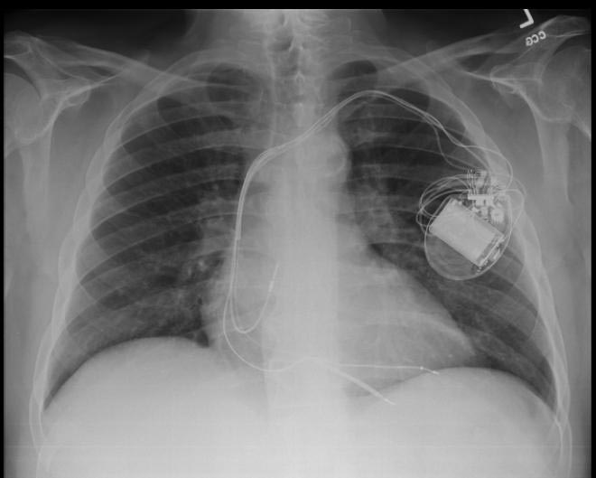
CXR showing Trilead cardiac pacer Image courtesy of RadsWiki and copylefted
-
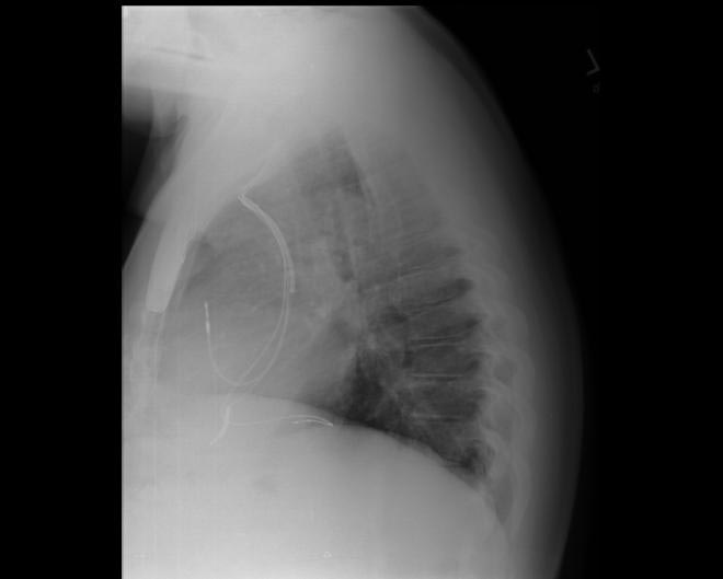
CXR showing Trilead cardiac pacer Image courtesy of RadsWiki and copylefted


Electrocardiogram
Shown below is an EKG demonstrating the determination of the atrial capture threshold. The pacemaker is decrementing down the atrial amplitude as marked below the atrial pacer spikes. Note the loss of atrial capture after the second spike of 1.5 volts. Loss of capture is illustrated by three events:
1) The lack of a P wave after the spike.
2) The appearance of a native P wave after the failure to capture.
3) The change in the RR intervals as the QRS is no longer following the paced P wave.
The lack of capture after the second 1.5 volt complex illustrates a component of time dependent capture where after a while a stimulus may fail to capture even thought the amplitude is kept constant.

Copyleft image obtained courtesy of ECGpedia, http://en.ecgpedia.org
Shown below is an EKG demonstrating threshold test of a VVI pacemaker. Note the effect of the PVCs, the first of which competes with the pacer stimulus and suggests capture when there may be none. Also note that the second to last 0.6 volt pulse captures the ventricle but the last, with the same pulse width, does not.

Copyleft image obtained courtesy of ECGpedia, http://en.ecgpedia.org
EKG Examples
Shown below is an EKG recorded from a patient in his 80's after implantation of a pacemaker. This recording was made as part of a routine pacemaker follow-up The pacing system was working well . This is an interesting electrocardiogram which illustrates an important point regarding pacemaker lead implantation. It is clear that this patient's pacemaker is sensing his P waves and following with pacing of his ventricle. What is curious about this recording, is the right bundle branch block configuration of the QRS and the extreme rightward axis seen in lead one. It is for this reason, a routine electrocardiogram] should be done after every pacemaker implantation that involves implanting a ventricular lead. In actual fact this patient's ventricular lead was pacing the left ventricle. This lead was probably in a branch of the coronary vein . The path of the lead can be traced by the CT video which was taken after this electrocardiogram was recorded. The patient had a pacemaker system that was working well, in spite of the fact that the pacemaker was pacing the left ventricle. In fact, new pacing techniques are pacing the left ventricle as well as the right ventricle to maintain cardiac synchronization. In this case though , the ventricular lead was removed, without complication, because of an associated infection of the pacemaker pocket.
A new pacemaker was implanted from the right side with the new lead placed in the right of ventricle. This resulted in a markedly different electrocardiogram.

Copyleft image obtained courtesy of ECGpedia, http://en.ecgpedia.org
Shown below is an EKG of a 21 year old patient during threshold testing in the pacemaker clinic. The patient had congenital heart block for which a pacemaker was implanted. She was asymptomatic before the implant, and a dizzy period during the test below.

Copyleft image obtained courtesy of ECGpedia, http://en.ecgpedia.org
Shown below is an EKG showing a tracing from the pacemaker clinic with the pacer set slightly below the threshold for capture. A magnet is over the pacemaker.

Copyleft image obtained courtesy of ECGpedia, http://en.ecgpedia.org
Shown below is an EKG showing a tracing from the pacemaker clinic with the pacer set slightly below the threshold for capture. A magnet is over the pacemaker.

Copyleft image obtained courtesy of ECGpedia, http://en.ecgpedia.org
Shown below is an EKG showing a tracing from the pacemaker clinic with a Medtronic model 8081 pacer set at 0.18ms @ 0.8 volts slightly below the threshold for capture. A magnet is over the pacemaker. (

Copyleft image obtained courtesy of ECGpedia, http://en.ecgpedia.org
Shown below is an EKG showing a tracing from the pacemaker clinic of a pacemaker set at 0.1ms slightly below the threshold for 100% capture. A magnet is over the pacemaker.

Copyleft image obtained courtesy of ECGpedia, http://en.ecgpedia.org
Shown below is an EKG example showing time dependent capture. The native QRS complexes are small (and grow larger due to the auto gain control on this recorder), and the rhythm is probably a nodal escape with sinus arrest. The pacer is a dual chamber where the atrial lead captures but the ventricular lead captures only if it falls close to a T wave of one of the native escape beats.

Copyleft image obtained courtesy of ECGpedia, http://en.ecgpedia.org
Shown below is an EKG example showing tracing in dual chamber pacemaker in an elderly man.

Copyleft image obtained courtesy of ECGpedia, http://en.ecgpedia.org
Shown below is an EKG example depicting an a rhythm strip recorded from a man attending the pacemaker follow-up clinic. The patient had been implanted with a ventricular pacemaker one week before. In the middle of the tracing a magnet was placed over the pacemaker.

Copyleft image obtained courtesy of ECGpedia, http://en.ecgpedia.org
Shown below is an EKG tracing taken from an 80 year old man with a Medtronic Model 8081 unipolar ventricular pacemaker. The patient had come to the clinic for a syncopal episode. During this recording the patient was doing an isometric exercise with his left arm.
The monitor, in this case a Medtronic programmer, adds markers to the EKG where it detects pacer spikes. These markers look like pacemaker spikes. Spike detection is controlled by the artifact setting in the programmer, and in some cases, such as in this case, over-detect ( as in the second spike seen above). The pacemaker was set to 60/min. and clearly there is a long period of inhibition of the pacemaker by the pectoral muscle with isometric exercise. This may have been related to the patient's symptoms. The problem was corrected by decreasing the sensitivity of the pacemaker.

Copyleft image obtained courtesy of ECGpedia, http://en.ecgpedia.org
Shown below is an EKG showing a recording from an elderly woman with complete heart block. She is having an Intermedics Quantum pacemaker (VVI) replaced with a Medtronic Preva DDD pacemaker. The Quantum is implanted in the left pectoral area and is set to V00 mode at 72/min, the Preva is implanted in the right pectoral area and set to VVI at 40/min. A magnet is placed over the Preva near the middle of the tracing. Both pacemakers are in a unipolar mode.
This is an interesting tracing as the two pacemaker leads where in a similar position in the left ventricle. This is clearly seen as the QRS morphology for both types of paced beats are identical. The morphology is a left bundle like pattern consistent with implantation of the electrode in the right ventricle as desired. Of interest is the difference in the polarity in lead I of the pacer spikes. The spike is positive for the pacer in the left pectoral region and negative for the pacer in the right pectoral area. As the pacemaker is the positive pole and the tip of the electrode the negative pole, this makes sense as lead I has a positive pole on the left shoulder and a negative one on the right.

Copyleft image obtained courtesy of ECGpedia, http://en.ecgpedia.org
Shown below is an EKG example of a ventricular paced rhythm, with visible ventricular pacemaker spikes.

Shown below is an EKG example showing a patient with a DDD type pace rhythm.

Copyleft image obtained courtesy of ECGpedia, http://en.ecgpedia.org
Shown below is an EKG demonstrating a patient with a VVI pacemaker rhythm. Note the LBBB morphology with left axis deviation indicating the pacing lead in the right ventricular apex.

Copyleft image obtained courtesy of ECGpedia, http://en.ecgpedia.org
Shown below is an EKG showing a ventricular paced rhythm.

Copyleft image obtained courtesy of ECGpedia, http://en.ecgpedia.org
Shown below 12 lead EKG in a person with a dual chamber pacemaker.

Shown below is an EKG from patient with a Medtronic model 8081 Premier single chamber pacemaker. The patient is a 65 year old man who had a history of blackouts while sitting. During the episodes his wife described him as becoming limp and white. His electrocardiogram showed a left bundle branch block with a normal PR interval. This conduction abnormality had been present for at least 16 years. An electrophysiology test was performed and a pacemaker inserted.

Copyleft image obtained courtesy of ECGpedia, http://en.ecgpedia.org
Shown below is an EKG showing a ventricular rate of about 72 beats/minute and it would appear that there is a p wave in front of each QRS complex. The "PR" interval is a little short at about 120 ms. The pacer should have started to pace the atrium when set at 100/min. The failure to do so suggests that the pacing system is non-functional (depleted pacemaker battery, broken lead etc.) or that the pacer is sensing an atrial rhythm faster than 100/min. In this case the pacer is sensing an SVT with an atrial rate of about 150/min. which explains the lack of pacing when the pacer is set to 100/min. The treating physician decided to leave the patient in this rhythm. It is interesting to note that some SVTs and atrial fibrillation can "cure" a sick sinus patient of their bradycardia and the need for a pacemaker. In those cases though that convert to atrial fibrillation anticoagulants are usually considered.

Copyleft image obtained courtesy of ECGpedia, http://en.ecgpedia.org
Shown below is an EKG example of myopotential inhibition of a VDD pacemaker in unipolar mode. This is a classic recording of myopotential inhibition of a pacemaker. Note the pacemaker that was following the patient's p waves for the first three beats, stops pacing as soon as the baseline records the "buzz" of the pectoral muscle activity. As the pacer stops pacing, the patient's underlying rhythm is seen which appears to be 2:1 Av block.

Copyleft image obtained courtesy of ECGpedia, http://en.ecgpedia.org
Shown below are two tracings from a patient with a history of torsade de pointes and complete heart block. These tracings are from a 24 hour Holter recording taken the day after a pacemaker clinic visit. The visit was prompted by a near syncopal episode. The pacing threshold measured in clinic was 0.15ms @ 1.6 volts and the patient was discharged with setting of 0.46ms @ 1.6 volts.

Copyleft image obtained courtesy of ECGpedia, http://en.ecgpedia.org
Shown below is an EKG example demonstrating the pacing threshold in a bipolar mode. The lead resistance was 1,140 ohms.

Copyleft image obtained courtesy of ECGpedia, http://en.ecgpedia.org
Shown below is an EKG demonstrating the pacing threshold in a unipolar mode.

Copyleft image obtained courtesy of ECGpedia, http://en.ecgpedia.org
Shown below is an EKG example where a magnet was placed over the pacemaker.

Copyleft image obtained courtesy of ECGpedia, http://en.ecgpedia.org
Shown below is an EKG of a part of a trans-telephonic strip in a patient with a pacemaker. This section was recorded with a magnet applied over the pacemaker which is a VVI pacemaker set at 50/min.

Copyleft image obtained courtesy of ECGpedia, http://en.ecgpedia.org
Shown below is an EKG strip recording from a patient checking his Medtronic VVI pacemaker. Part of the printout of the rhythm strip is below.Note the 4 fast beats at 100/min near the end of the recording indicating that the patient has placed the magnet properly over the pacemaker.

Copyleft image obtained courtesy of ECGpedia, http://en.ecgpedia.org
Shown below is an EKG tracing form the pacemaker clinic. The patient has a VVI Medtronic pacemaker which was probably set at 70/min. A magnet is placed over the pacemaker and results in a magnet response of 4 beats at 90/min, and then a paced rhythm at about 63/min.

Copyleft image obtained courtesy of ECGpedia, http://en.ecgpedia.org
Shown below is an EKG strip recording from a patient with a pacemaker. The reason why the pacer was pacing at 75/min in the DDD mode was because there is a supraventricular tachycardia (note atrial activity, marked with the turqouise arrows, moving through the ventricular complexes) at about 150/min and the DDD pacer was producing 2:1 A/V block. In the tracing above with the pacemaker set to a VVI mode, the pacemaker no longer senses the atrium and paces at the set rate of 70/min.

Copyleft image obtained courtesy of ECGpedia, http://en.ecgpedia.org
Shown below is an EKG from a patient with a Medtronic model 7108 Minuet dual chamber pacemaker. The patient had intact A/V conduction, and with a long paced A/V interval, conducted paced atrial beats to the ventricle. The atrial pacing threshold was determined by pacing at a rate faster than the patient's own rate and decreasing the atrial pulse width until atrial capture was lost, and ventricular pacing occurred (the upper tracing).In spite of returning the atrial pulse width back to the last successful value, ventricular pacing continued .Slowing the pacing rate terminated ventricular pacing (the lower tracing) and ventricular pacing did not return when the pacing rate was speeded up again.

Copyleft image obtained courtesy of ECGpedia, http://en.ecgpedia.org
Shown below is an EKG from a patient with a Medtronic model 8081 Premier single chamber pacemaker. The patient is a 65 year old man who had a history of blackouts while sitting. During the episodes his wife described him as becoming limp and white. His electrocardiogram showed a left bundle branch block with a normal PR interval. This conduction abnormality had been present for at least 16 years.An electrophysiology test was performed and a pacemaker inserted.

Copyleft image obtained courtesy of ECGpedia, http://en.ecgpedia.org
Shown below is an EKG rhythm strip recorded from a man attending the pacemaker follow-up clinic. The Patient had been implanted with a ventricular pacemaker one week before. In about the middle of the tracing a magnet was placed over the pacemaker.

Copyleft image obtained courtesy of ECGpedia, http://en.ecgpedia.org
Shown below is an EKG rhythm strip recorded from a man attending the pacemaker follow-up clinic. The patient had been implanted with a dual chamber pacemaker one month before. The pacer was programed to VVI mode and AAI mode and ECG recordings were made. Also a PA and lateral chest x-ray was taken.

Copyleft image obtained courtesy of ECGpedia, http://en.ecgpedia.org
Shown below is an EKG rhythm strip of a threshold determination in a patient with a temporary (epicardial) ventricular pacemaker. The epicardial pacemaker leads were placed after the patient collapsed during aortic valve surgery. In the first half of the tracing, pacemaker stimuli at 60 beats per minute result in a wide QRS complex with a right bundle branch block pattern. Progressively weaker pacing stimuli are administered, which results in asystole in the second half of the tracing. At the end of the tracing, distortion results from muscle contractions due to a (short) hypoxic seizure. Because decreased pacemaker stimuli do not result in a ventricular escape rhythm, the patient can be said to be pacemaker-dependent and needs a definitive pacemaker.

Copyleft image obtained courtesy of ECGpedia, http://en.ecgpedia.org
Shown below is an EKG recording of two permanent pacemakers working at the same time. The ventricular pacemaker at a rate of 40/min., while the dual chamber pacer is set at a rate of about 80/min with an AV interval of about 160 ms. The atrial lead of the dual chamber pacemaker is capturing and sensing the atrium. The ventricular lead is not capturing the ventricle. There is no native rhythm from the patient seen here.

Copyleft image obtained courtesy of ECGpedia, http://en.ecgpedia.org
Shown below is an EKG depicting the potential spikes due to a pacemaker. The extra spikes that you see are from a myoplasty stimulator. This is a stimulator used to stimulate a muscle wrapped around the heart. It is stimulating the muscle every second beat. A train is used as this is a skeletal muscle and not heart muscle.

Copyleft image obtained courtesy of ECGpedia, http://en.ecgpedia.org
Shown below is an EKG showing the ladder diagram and surface tracing from a patient with a dual chamber pacemaker. The pacer is pacing the atrium (star) and sensing the ventricle. Note the refractory periods (boxes) of the atrium and the ventricle and the post ventricular atrial refractory period.

Copyleft image obtained courtesy of ECGpedia, http://en.ecgpedia.org
Shown below is an EKG demonstrating time dependent capture. Note the the venticular pacemaker captures for several beats but then fails to capture. Capture is restored when the pacer spike falls near to a conducted sinus beat. The underlying rhythm shows a lengthening of the PR interval before a P wave fails to conduct. This suggests a Mobitz I A/V block

Copyleft image obtained courtesy of ECGpedia, http://en.ecgpedia.org
Shown below is an EKG recording from the atrial lead of a dual chamber pacemaker where the patient is in atrial fibrillation. Note the substantial and rapid atrial signal.

Copyleft image obtained courtesy of ECGpedia, http://en.ecgpedia.org
Shown below is an EKG recording from a patient coming for a routine DDD pacemaker check.

Copyleft image obtained courtesy of ECGpedia, http://en.ecgpedia.org
Shown below is an EKG with a magnet placed over the pacemaker that was set at 30/min. Hence it is pacing at 30/min and is not affected by the native sinus beats. This is an interesting case of group beating. The sinus beats are locked into the step with the ventricular pacemaker and suggests an effect of the ventricular paced complex on the sinus node, perhaps as seen with the ventriculophasic effect.

Copyleft image obtained courtesy of ECGpedia, http://en.ecgpedia.org
Shown below is an intra-operative EKG recording taken during testing of an internal defibrillation system.

Copyleft image obtained courtesy of ECGpedia, http://en.ecgpedia.org
2012 ACCF/AHA/HRS Focused Updates Incorporated With 2008 Guidelines for Device-Based Therapy of Cardiac Rhythm Abnormalities (DO NOT EDIT)[27][28]
Permanent Pacing in Sinus Node Dysfunction[28]
Acquired Atrioventricular Block in Adults[28]
Permanent Pacing in Chronic Bifascicular Block[28]
Permanent Pacing After the Acute Phase of Myocardial Infarction[28]
Permanent Pacing in Hypersensitive Carotid Sinus Syndrome and Neurocardiogenic Syncope[28]
Pacing After Cardiac Transplantation[28]
Permanent Pacemakers That Automatically Detect and Pace to Terminate Tachycardias[28]
Pacing to Prevent Tachycardia[28]
CRT in Patients With Systolic Heart Failure[27]
Pacing in Patients With Hypertrophic Cardiomyopathy[28]
Permanent Pacing in Children, Adolescents, and Patients With Congenital Heart Disease[28]
Implantable Cardioverter-Defibrillators[28]
Implantable Cardioverter-Defibrillators in Pediatric Patients and Patients With Congenital Heart Disease[28]
Related Chapters
References
- ↑ McWilliam JA (1889). "Electrical stimulation of the heart in man". Br Med J. 1: 348–50.
|access-date=requires|url=(help). Partial quote in "Electrical Stimulation of the Heart in Man - 1889", Heart Rhythm Society, Accessed May 11, 2007. - ↑ Lidwell M C, "Cardiac Disease in Relation to Anaesthesia" in Transactions of the Third Session, Australasian Medical Congress, Sydney, Australia, Sept. 2-7 1929, p 160.
- ↑ 3.0 3.1 Mond H, Sloman J, Edwards R (1982). "The first pacemaker". Pacing and clinical electrophysiology : PACE. 5 (2): 278–82. PMID 6176970.
- ↑ Aquilina O, "A brief history of cardiac pacing", Images Paediatr Cardiol 27 (2006), pp.17-81.
- ↑ Furman S, Szarka G, Layvand D, "Reconstruction of Hyman's second pacemaker", Pacing Clin Electrophysiol.2005 May;28(5):446-453
- ↑ http://www.hno.harvard.edu/gazette/2001/04.19/12-zoll.html
- ↑ Weirich W, Gott V, Lillehei C: The treatment of complete heart block by the combined use of a myocardial electrode and an artificial pacemaker. Surg. Forum 1957;8;360-363
- ↑ "Furman S, Schwedel JB" An intracardiac pacemaker for Stokes-Adams Seizures N Eng J Med 1959; 261:943-948"
- ↑ "Permanent Transvenous Pacing in 1962", Parsonnet V, PACE,1:285, 1978
- ↑ "Preliminary Investigation of the Development of a Permanent Implantable Pacemaker Using an Intracardiac Dipolar Electrode", Parsonnet V, Zucker I R, Asa M M, Clin. Res., 10:391, 1962
- ↑ "How It Happened: My Recollection of Early Pacing", Lageren H, PACE: Pacing and Clinical Electrophysiology 1.1, Jan. 1978, pp 140-143
- ↑ "Intracardiac Stimulation for Complete Heart Block", Lageren H, Acta. Chir. Sca., 125:562, 1963
- ↑ Jean Jaques Welti:Biography, Heart Rhythm Foundation
- ↑ (Cite_Journal)Percussion pacing in a three year-old girl with complete heart block during cardiac catheterization. C Eich, A Bleckmann and T. Paul, retrieved from http://bja.oxfordjournals.org/cgi/content/full/95/4/465
- ↑ Bernstein A, Daubert J, Fletcher R, Hayes D, Lüderitz B, Reynolds D, Schoenfeld M, Sutton R (2002). "The revised NASPE/BPEG generic code for antibradycardia, adaptive-rate, and multisite pacing. North American Society of Pacing and Electrophysiology/British Pacing and Electrophysiology Group". Pacing Clin Electrophysiol. 25 (2): 260–4. PMID 11916002.
- ↑ Cleland JG, Daubert JC, Erdmann E; et al. (2005). "The effect of cardiac resynchronization on morbidity and mortality in heart failure". N. Engl. J. Med. 352 (15): 1539–49. doi:10.1056/NEJMoa050496. PMID 15753115.
- ↑ Bardy GH, Lee KL, Mark DB; et al. (2005). "Amiodarone or an implantable cardioverter-defibrillator for congestive heart failure". N. Engl. J. Med. 352 (3): 225–37. doi:10.1056/NEJMoa043399. PMID 15659722.
- ↑ Cleland J, Daubert J, Erdmann E, Freemantle N, Gras D, Kappenberger L, Tavazzi L (2005). "The effect of cardiac resynchronization on morbidity and mortality in heart failure". N Engl J Med. 352 (15): 1539–49. doi:10.1056/NEJMoa050496. PMID 15753115.
- ↑ Bristow M, Saxon L, Boehmer J, Krueger S, Kass D, De Marco T, Carson P, DiCarlo L, DeMets D, White B, DeVries D, Feldman A (2004). "Cardiac-resynchronization therapy with or without an implantable defibrillator in advanced chronic heart failure". N Engl J Med. 350 (21): 2140–50. doi:10.1056/NEJMoa032423. PMID 15152059.
- ↑ Wilkoff BL, Cook JR, Epstein AE; et al. (2002). "Dual-chamber pacing or ventricular backup pacing in patients with an implantable defibrillator: the Dual Chamber and VVI Implantable Defibrillator (DAVID) Trial". JAMA. 288 (24): 3115–23. PMID 12495391. Unknown parameter
|month=ignored (help) - ↑ 21.0 21.1 Bernstein A, Camm A, Fisher J, Fletcher R, Mead R, Nathan A, Parsonnet V, Rickards A, Smyth N, Sutton R (1993). "North American Society of Pacing and Electrophysiology policy statement. The NASPE/BPEG defibrillator code". Pacing Clin Electrophysiol. 16 (9): 1776–80. PMID 7692407.
- ↑ European Pacemaker Patient Identification card
- ↑ Eucomed
- ↑ "Testing of work environments for electromagnetic interference (Pacing Clin Electrophysiol. 1992) - PubMed Result". www.ncbi.nlm.nih.gov. Retrieved 2008-11-10.
- ↑ "MP3 Headphones Interfere With Implantable Defibrillators, Pacemakers - Beth Israel Deaconess Medical Center". www.bidmc.org. Retrieved 2008-11-10.
- ↑ 26.0 26.1 Halperin, Daniel (2008). Pacemakers and Implantable Cardiac Defibrillators: Software Radio Attacks and Zero-Power Defenses (PDF). IEEE Symposium on Security and Privacy. Retrieved 2008-08-10. Unknown parameter
|month=ignored (help); Unknown parameter|coauthors=ignored (help) - ↑ 27.0 27.1 Tracy CM, Epstein AE, Darbar D, Dimarco JP, Dunbar SB, Estes NA, Ferguson TB, Hammill SC, Karasik PE, Link MS, Marine JE, Schoenfeld MH, Shanker AJ, Silka MJ, Stevenson LW, Stevenson WG, Varosy PD (2012). "2012 ACCF/AHA/HRS Focused Update of the 2008 Guidelines for Device-Based Therapy of Cardiac Rhythm Abnormalities: A Report of the American College of Cardiology Foundation/American Heart Association Task Force on Practice Guidelines". Heart Rhythm. 9 (10): 1737–53. doi:10.1016/j.hrthm.2012.08.021. PMID 22975672. Retrieved 2012-11-01. Unknown parameter
|month=ignored (help) - ↑ 28.00 28.01 28.02 28.03 28.04 28.05 28.06 28.07 28.08 28.09 28.10 28.11 28.12 Epstein AE, Dimarco JP, Ellenbogen KA, Estes NA, Freedman RA, Gettes LS; et al. (2008). "ACC/AHA/HRS 2008 guidelines for Device-Based Therapy of Cardiac Rhythm Abnormalities: executive summary". Heart Rhythm. 5 (6): 934–55. doi:10.1016/j.hrthm.2008.04.015. PMID 18534377.